Advancing the effective use of light for society and the environment

|
|
Advancing the effective use of light for society and the environment |
|
|
|
||
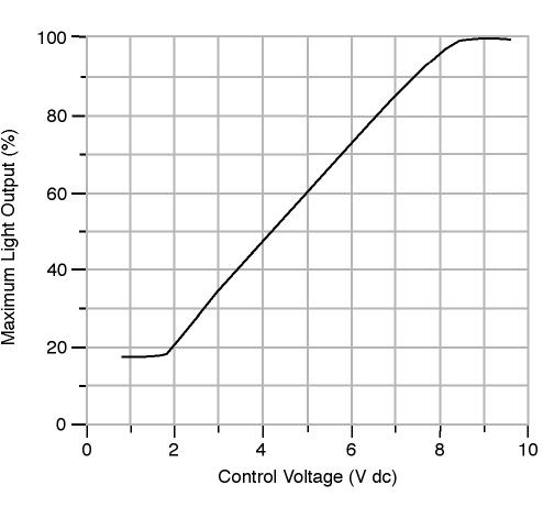
CharacteristicsAs evident from the system diagram, the photosensor embodies a number of different functional elements of the complete system. Photosensor versus photocellIn this tutorial, the term photocell refers only to the light sensitive component inside the photosensor. The term photosensor is used to describe an entire product including the housing, optics, electronics, and the photocell. Input characterizationThe input to a photosensor is optical radiation. Loosely speaking, the input is light, but because some photosensors respond to infrared (IR) and ultraviolet (UV) radiation as well, it is necessary to make a distinction between optical radiation that is visible light and other kinds of optical radiation. The response of a photosensor to optical radiation is fully described by the spatial response and the spectral response. Output characterizationThe photosensor output is a control signal that is sent to a dimming ballast or any device that actively controls the electric light level. The control algorithm of a photosensor describes the exact nature of the output control algorithm as a function of the input to a photosensor. Effect of photosensor output on light levelFor dimming systems, the dimming ballast controls the electric light level based on input from the photosensor. The amount of dimming as a function of input signal is characterized by the dimming response function. For many dimming ballasts the dimming response function is linear, meaning that it reduces the electric light level in proportion to the input signal. However, the active input dimming range is usually less than the specified range of input control voltage. For example, for a ballast with an input signal specification of zero to 10 V, dimming actually takes place over a more limited range from about 1.5 V (minimum light output) to 8.5 V (maximum light output). The figure below shows the typical dimming response of an electronic dimming ballast.
|
|||
|
|||
|
|
Contact Us | Privacy | © 1995-2023 Rensselaer Polytechnic Institute, Troy, NY 12180 USA - All rights reserved
|