Advancing the effective use of light for society and the environment

|
|
Advancing the effective use of light for society and the environment |
|
|

|
||
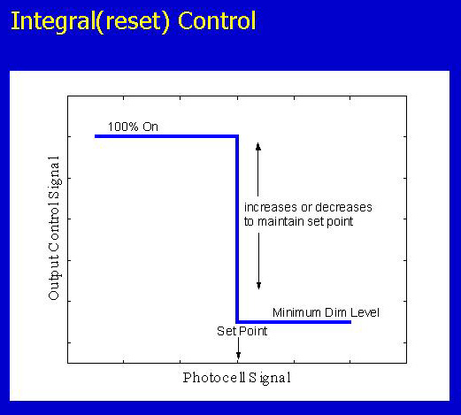
Control Algorithm, continuedIntegral (reset)The integral (reset) control is intended for closed-loop systems. In a closed-loop system, the control voltage continuously increases or decreases to maintain a constant optical signal on the photosensor. The integral (reset) control has one adjustable parameter, the set point. Therefore, commissioning an integral (reset) photosensor involves setting this one set point. The optical signal on the photosensor remains constant as long as the required level of electric light is within the dimming range of the ballast.
If the electric light level cannot be increased enough to maintain a constant photosensor signal, the control voltage stays at the maximum level and the photosensor signal falls below the set point. Conversely, if the electric light level cannot be dimmed enough to maintain a constant photosensor signal, meaning that more than enough daylight is present to provide the constant photosensor signal, then the control voltage stays at a minimum level and the photosensor signal increases beyond the set point. In other words, the photosensor-dimming ballast system has a certain operating range over which it will maintain a constant optical signal on the photosensor. The operating range is determined mainly by the dimming ballast with a corresponding range from 100% electric light output down to the minimum dimming level (typically 5 to 20% of maximum light output). Consequences of integral (reset) controlThe integral (reset) control algorithm maintains the optical signal on the photosensor as constant as possible. However, the optical signal on the photosensor does not correspond, in most cases, to the workplane illuminance for a number of reasons. First, and most importantly, the location of the photosensor is usually not on the workplane but instead on the ceiling or wall. Changes in ceiling illuminance do not correspond well with changes in workplane illuminance. This discrepancy is caused by the different light distribution within a room when daylight is present compared to electric light alone. In most rooms the ceiling illuminance increases much more than the workplane illuminance as daylight enters the space (see system components). Therefore, a control algorithm that maintains a constant optical signal on the photosensor, which is similar to keeping a constant ceiling illuminance, will result in the workplane illuminance falling much below the target value as daylight enters the room. Second, the spatial response of photosensors is not equal to that of an illuminance meter (it is not a cosine response). A photosensor might respond differently to the different distributions of light from electric and daylight sources even for the same illuminance at the photosensor. A spatial response different than that of an illuminance meter is often beneficial and a narrow response can help the system track workplane illuminance but too narrow a response can lead to other problems. Third, the spectral response of photosensors does not match that of an illuminance meter (it does not match the photopic response well). The optical signal that is maintained will not correspond to a constant illuminance level. Most photosensors are 30 to 40% more sensitive to daylight than to electric light for the same illuminance (see section on spectral response). Because the response to daylight is usually greater than to electric light, the integral(reset) control algorithm causes the electric lights to dim too much in the presence of daylight. This effect compounds the problems of excessive dimming caused by the changing workplane/ceiling illuminance ratios discussed above. More information on integral (reset) control. |
|||
|
|||
|
|
Contact Us | Privacy | © 1995-2023 Rensselaer Polytechnic Institute, Troy, NY 12180 USA - All rights reserved
|